
N1060KRCC9P4 cylindrical roller bearing 300×460mm
News & Updates
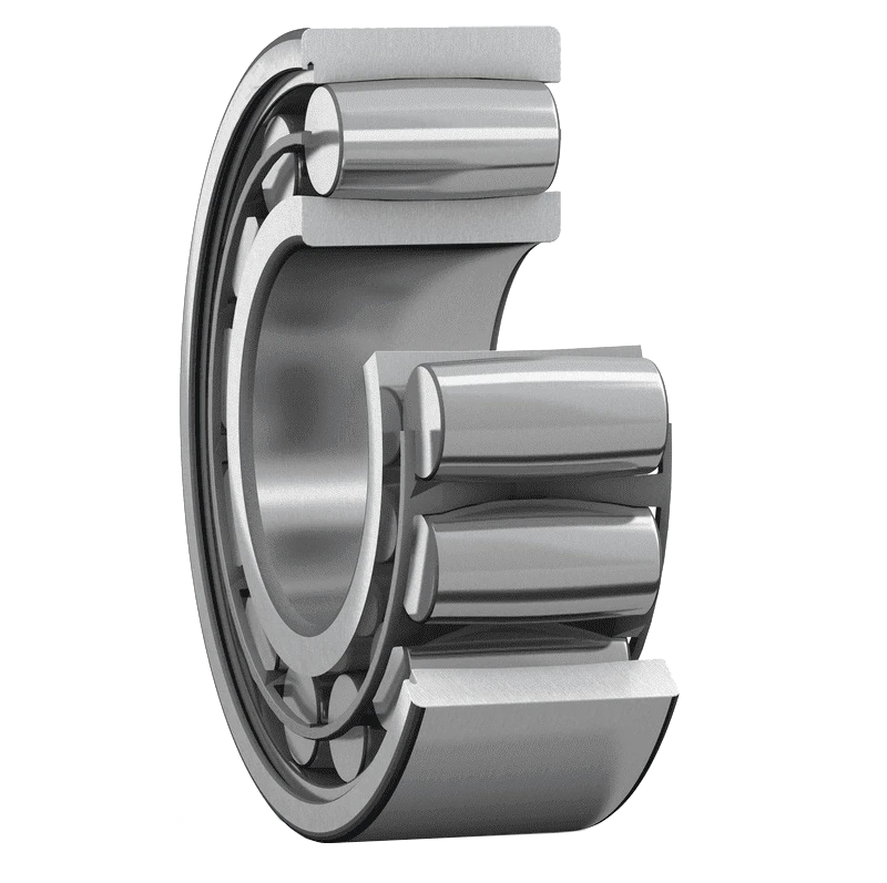
N1060KRCC9P4 cylindrical roller bearing 300×460mm
Q: Can I directly swap this unit with older stock without machining adjustments? A: Yes, provided you verify the dimensional tolerances and shaft interference requirements before installation. This inquiry regularly appears in maintenance planning sessions when engineers audit inventory for obsolete or discontinued components. The N1060KRCC9P4 remains highly sought after because its architecture aligns closely with legacy European design specifications, though modern supply chains often rely on standardized interchange matrices rather than blind substitution. When evaluating replacements, we examine the base profile, raceway curvature, and clearance classes to determine true cross-equivalence. Many procurement teams overlook that even millimeter deviations in width or bore angle can trigger premature cage wear or localized stress concentrations under heavy radial loads. Proper cross-referencing demands more than matching outside diameters. It requires validating the internal geometry against your specific operating environment. This is why understanding the interchange protocol behind every designation becomes critical for reducing unplanned downtime.
At a glance
- Parameter: Value
- Series: N10 sereis (N10..KRCC9P4)
- Dimensions (d×D×B): d:300 × D:460 × B:74
- Weight: 42.2 kg
What Is the Direct Equivalent for the N1060KRCC9P4 in Modern Interchange Programs?
Interchange programs function on a hierarchical classification system where series prefixes dictate fundamental load geometry, while suffix codes communicate cage composition, tolerance grades, and internal clearance modifications. The N1060KRCC9P4 belongs to the N10 series family, which establishes a narrow-width, single-row cylindrical roller configuration optimized for high rigidity and minimal rotational resistance. Cross-referencing this component begins with identifying the baseline series code, then mapping each suffix element to its functional counterpart in competing manufacturing standards. Original European design documentation typically pairs the KRCC9P4 designation with P4 precision grading and a chromium carbide case-hardened steel ring treatment. Modern interchange matrices translate these parameters into standardized tolerance bands, allowing maintenance planners to substitute units across supplier networks without compromising axis alignment.
Navigating bearing number reference guides reveals that many legacy part numbers have been consolidated into unified series designations. Procurement departments frequently encounter fragmentation when auditing multi-site inventories, as historical catalogs retain proprietary numbering conventions while contemporary logistics favor alphanumeric series tracking. Mapping the N1060KRCC9P4 to current catalog structures requires isolating the core dimensional series, verifying the precision grade classification, and confirming the internal clearance specification. Once these three variables align, the substitute component enters active interchange consideration. Engineers should always validate heat treatment specifications alongside dimensional matching, as thermal stability directly influences bore retention forces during high-cycle operations. Skipping this validation step often results in axial shift under rapid acceleration cycles, especially when operating within steep temperature gradients.
Dimensional Tolerances and Bore Geometry Comparison
Structural interchangeability hinges primarily on dimensional fidelity and mounting interface compatibility. The following specification matrix outlines the core geometric parameters governing replacement eligibility:
| Parameter | Value |
|---|---|
| Series | N10 sereis (N10..KRCC9P4) |
| Dimensions (d×D×B) | d:300 × D:460 × B:74 |
| Weight | 42.2 kg |
| Bore Type | KR = 1/12 Tapered bore |
| Inside Diameter | 300 mm |
| Outside Diameter | 460 mm |
| Thickness Width | 74 mm |
Matching the inner diameter alone does not guarantee successful interchange. The 1/12 tapered bore configuration introduces controlled interference compression when drawn onto a matching tapered adapter sleeve or machined spindle shoulder. Substitutes lacking identical taper angles or surface finish requirements will produce uneven clamping pressure, resulting in fretting corrosion or asymmetric roller skewing. Precision machining facilities typically specify H6 or g6 shaft tolerance grades for this geometry, ensuring predictable preload distribution without excessive friction heating. When selecting cross-referenced units, verify that the replacement catalog lists equivalent tolerance classifications and taper conformity metrics.
Tolerance stack-up calculations become particularly relevant in high-speed rotary applications where centrifugal expansion alters internal clearances. A deviation of merely five microns in raceway radius can shift contact angles enough to alter lubricant film thickness dynamics. Engineers auditing replacement batches should measure bore concentricity using dial indicators or coordinate measuring machines before committing to field installation. Documented interchange failures most commonly trace back to overlooked dimensional variances rather than material incompatibility. Maintaining rigorous measurement protocols protects against cascading mechanical degradation downstream.
Load Capacity and Speed Limitations Across Standard Replacements
Radial load performance defines the operational envelope for nearly every cylindrical roller implementation. The base unit delivers a basic dynamic load rating of 884,741 N and a basic static load rating of 1,399,706 N, establishing a substantial margin for heavy-duty machining centers and turbine auxiliary drives. Interchange substitutes must match or exceed these thresholds while preserving the same contact angle geometry. Downgrading load capacity to accommodate cost reduction strategies invariably reduces service life proportionally, particularly under combined axial-radial loading scenarios common in pump assemblies and gear reducers.
Speed parameters operate within stricter boundaries due to centrifugal forces acting on the rolling elements and cage assembly. The reference speed of 1,788 r/min assumes grease lubrication and ambient thermal conditions, while the limiting speed of 2,183 r/min reflects oil mist or circulating oil environments capable of extracting heat faster than conduction through the housing. Cross-referencing speed limitations requires careful evaluation of your actual lubrication regime, housing ventilation design, and duty cycle frequency. Operating consistently beyond reference speeds accelerates fatigue spalling in the raceways, whereas running significantly below limiting speeds offers minimal efficiency gains unless thermal management dictates otherwise. Engineers planning equipment retrofits should calculate adjusted speed ratings using ISO application factors that account for viscosity changes, contamination levels, and preload configurations. Validating speed compatibility prevents unexpected vibration signatures during commissioning phases.
Cage Design and Rib-Guidance Interchangeability Factors
The brass cage with rib guidance architecture represents a deliberate engineering choice aimed at balancing strength, friction reduction, and thermal conductivity. Brass compositions provide inherent lubricity that minimizes cage-to-roller friction during boundary lubrication states, which frequently occur during startup transients or emergency stops. The rib guidance mechanism ensures consistent roller alignment along the raceway path, preventing skidding and reducing localized stress concentrations that initiate micro-cracking. When evaluating interchangeable alternatives, confirm whether the substitute utilizes machined brass, stamped polymer, or forged steel construction, as each material reacts differently to thermal cycling and vibration frequencies.
Rib guidance geometry also dictates maximum permissible angular misalignment during operation. Standardized designs typically tolerate up to three arcminutes of shaft-to-housing parallelism error before cage deflection triggers excessive contact pressure. Substitutes featuring altered rib heights or modified guide groove radii may appear dimensionally compatible while failing internally under dynamic loading. Verification requires cross-referencing cage profile drawings alongside dimensional catalogs rather than relying solely on external measurements. Proper interchange selection preserves the original kinematic behavior of the rolling contact system, maintaining predictable wear progression and extending mean time between failures. Upgrading to reinforced rib structures occasionally improves durability, but only when validated against your specific load spectra and operating temperatures.
For comprehensive compatibility charts and updated interchange guidelines, consult our Cylindrical roller bearings, single row, super-precision category. Reviewing manufacturer application notes alongside your site-specific maintenance logs provides valuable context when troubleshooting recurring bearing failures. Many documented interchange issues stem from mismatched preload expectations rather than raw dimensional discrepancies. Adjusting nut torque sequences or utilizing calibrated hydraulic draw-in methods often resolves misalignment complaints without requiring component swaps.
Selecting the Right Substitute for High-Precision Applications
Finalizing an interchange decision requires synthesizing dimensional data, load capabilities, lubrication requirements, and historical performance records. Engineering teams should establish a standardized verification checklist that covers bore taper angles, raceway curvature tolerances, cage material specifications, and precision grade markings. Documenting each parameter eliminates guesswork during emergency replacements and streamlines future procurement cycles. When multiple equivalent models satisfy baseline requirements, prioritize units offering improved seal compatibility or enhanced corrosion resistance if your environment presents moisture exposure or chemical contaminants.
Implementing a structured cross-reference workflow reduces reliance on emergency spot purchasing and stabilizes inventory forecasting. Maintenance planners benefit from maintaining approved substitute lists for critical production assets, ensuring continuity when primary suppliers experience lead time delays. Regularly updating these matrices with newly released catalogs and revised tolerance standards keeps your interchange program responsive to manufacturing advancements. Engaging directly with specialized engineering support provides clarity on edge cases where theoretical compatibility meets practical installation realities. For detailed cross-reference matrices and technical consultation tailored to your machinery layout, visit FIJ Bearing to explore precision components engineered for demanding industrial applications.
Request a quote from FIJ Bearing for certified interchangeable units matched to your exact operational parameters.