
71916 angular contact ball bearing 80×110mm
News & Updates
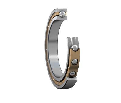
71916 angular contact ball bearing 80×110mm
Load Distribution vs Generic Alternatives
Standard deep groove bearings handle radial loads efficiently but suffer catastrophic failure under combined loading in high-speed spindles. The 71916 angular contact ball bearings, super-precision variant is engineered to sustain significant axial forces while maintaining micron-level geometric stability. When vibration spikes appear prematurely, the root cause rarely lies in material hardness; instead, it points to preload miscalibration or housing misalignment that forces the contact angle outside its optimal engagement zone.
At a glance
- Parameter: Value
- Inside Diameter (d): 80 mm
- Outside Diameter (D): 110 mm
- Width (B): 16 mm
Engineers selecting components from general catalogs often underestimate the sensitivity of super-precision designs to peripheral errors. Visiting our Angular contact ball bearings, super-precision category highlights the stringent manufacturing tolerances required to replicate the original European design performance without compromising service life.
Raceway Fatigue and Axial Play
The characteristic contact angle directs load paths radially inward. Non-coaxial mounting creates edge stresses that initiate micropitting within hours of operation. These surface fractures propagate into spalling events that generate audible noise and heat. Operators frequently attribute this damage to lubricant breakdown, yet improper interference fit on the cylindrical bore shifts the effective load zone toward the raceway edges.
Excessive tightening of locking nuts increases preload beyond design limits, reducing internal clearance to negative values. This compression elevates friction torque and accelerates fatigue cycling. Diagnosing spalling requires inspecting the orientation of wear scars relative to the load vector to distinguish between fit errors and genuine overload conditions.
Cage Integrity and Lubrication Strategies
Cage material selection directly influences speed capability and damping characteristics. Options for this model include cotton fabric reinforced phenolic resin or carbon fibre reinforced PEEK, both featuring outer ring centring. Phenolic constructions offer excellent damping for moderate speeds but may degrade under sustained thermal stress. Carbon-fibre PEEK cages resist centrifugal lifting forces, making them suitable for higher rotational velocities, though they transmit shock loads differently to the balls.
Cage wear often manifests as rivet loosening or discoloration, signaling lubrication gaps. Thick oils create hydrodynamic drag, while insufficient viscosity breaks down the elastohydrodynamic film. Since the unit utilizes an open sealing configuration, abrasive ingress remains a critical risk. Implementing robust external shielding or compressed air purging protects these sensitive interfaces. Verifying your exact specification through our bearing number reference ensures you match the correct cage variant to your duty cycle.
Specification Matrix and Thermal Limits
Maintaining operational parameters within defined boundaries prevents thermal runaway and clearance loss. Verify inventory items against these core attributes before installation:
| Parameter | Value |
|---|---|
| Inside Diameter (d) | 80 mm |
| Outside Diameter (D) | 110 mm |
| Width (B) | 16 mm |
| Weight | 0.367 kg |
| Operating Temperature | -30 ~ 110 °C |
| Sealing | Open |
| Bore Type | Cylindrical |
| Series Designation | 719..ACDGA/VQ253 |
Temperature excursions beyond 110 °C degrade lubricant additives and alter dimensional stability. Inner rings expand faster than outer housings due to mass differences, further reducing internal play. Calculate differential expansion during the design phase to ensure adequate clearance survives thermal equilibrium.
Rapid Diagnostic Protocol
Before disassembly, correlate vibration signatures with operating conditions to isolate failure drivers. High-frequency bands typically indicate rolling element defects, while low-amplitude modulations suggest lubrication starvation. Execute this checklist to validate installation quality:
- Inspect housing roundness and seat finish against ISO surface roughness requirements.
- Measure shaft diameters with calibrated gauges to confirm proper interference fit magnitude.
- Audit auxiliary seals and labyrinths for leakage paths that invite contaminant entry.
- Rotate the assembly by hand immediately after mounting to detect binding or rough spots.
- Record thermal readings during the first hour of run-in to confirm stable friction levels.
Systematic documentation of operating parameters and failure timelines significantly reduces recurrence rates. For precise replacements that meet strict dimensional tolerances and material specifications, request a quote for replacement units from FIJ.