
NGCRM slewing bearing 1412×1680mm
News & Updates
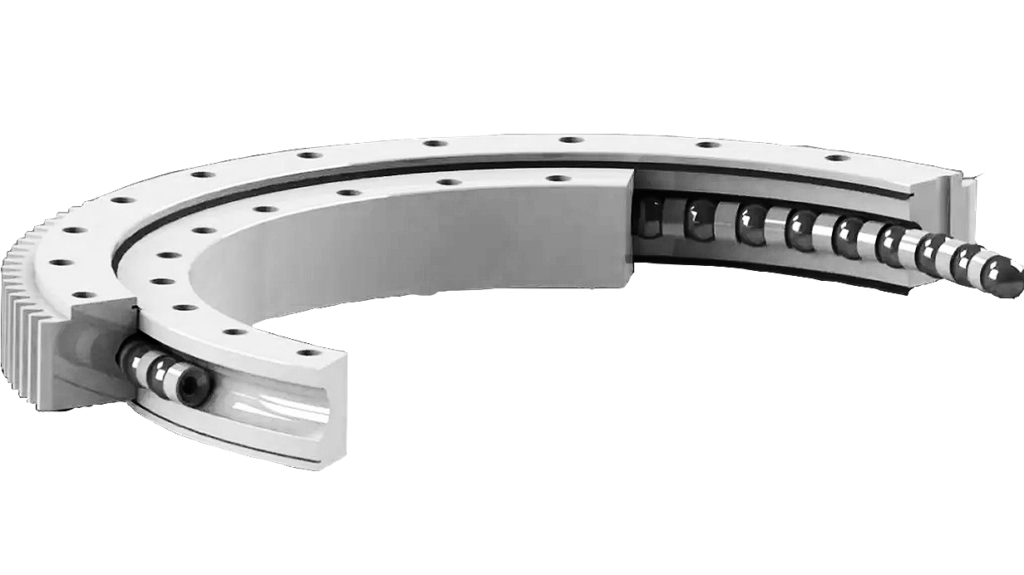
NGCRM slewing bearing 1412×1680mm
Overcoming Combined Load Deflection in Rotary Actuators
Machine tool turntables and articulated robot bases routinely experience simultaneous axial thrust, radial offset, and tilting moments during rapid deceleration. Traditional single-vane configurations develop micro-clearance under these vector combinations, causing positional drift and accelerated wear. Integrating a single-row crossed roller arrangement directly into the kinematic chain eliminates intermediate backlash pathways while forcing orthogonal contact angles to share the mechanical burden. This geometry locks onto rigid mating flanges through precision-ground raceways, guaranteeing that every rotation cycle maintains constant preload regardless of directional shifts. Engineers documenting component identifiers under our Crossed roller slewing bearings (No gear type) category.
At a glance
- Machine tool turntables and articulated robot bases routinely experience simultaneous axial thrust, radial offset, and t
- Component | Specification | Engineering Note— | — | —Inner Diameter | 1412 mm | Permits unrestricted cable routing or ho
Component | Specification | Engineering Note
— | — | —
Inner Diameter | 1412 mm | Permits unrestricted cable routing or hollow shaft passage
Outer Diameter | 1680 mm | Matches legacy machine base plate drilling patterns
Section Width | 70 mm | Prevents excessive bending moments under eccentric loads
Operating Weight | 725 kg | Requires reinforced mounting subframes
Compact sectional profiles minimize overall equipment depth without sacrificing load capacity. Standardizing on these exact boundary values streamlines jig fabrication and suppresses non-recurring engineering expenditures. Every machining datum must reference the neutral axis positioned exactly between the two diameter extremes.
Axial Static Load Capacity & Stress Limits
Static resistance delivers six million one hundred seventy thousand newtons along the central axis. This rating assumes uniform pressure distribution across the forty-five-degree contact zones established by alternating roller placement. The perpendicular crossing pattern absorbs tilting moments and radial offsets simultaneously, preventing cage collision during multi-axis maneuvers. Selecting the proper precision grade directly correlates with friction behavior and running accuracy under peak static stress. P0 suits general industrial cycling, P6 serves automated assembly sequences, and P5 targets metrology platforms where micron-level repeatability defines throughput. Polymer cage alternatives ranging from PA6 to PA1010 and PVC allow thermal expansion matching for extended duty cycles or specific lubrication regimens.
Rotational Velocity Thresholds
Operational speed must remain strictly proportional to centrifugal forces exerted on the crossing rollers. Pushing beyond engineered limits generates conductive heat that degrades polymer retainers and expands raceway geometries outside acceptable tolerance bands. For this seventy-millimeter section profile, sustained velocities generally remain below two revolutions per minute when loaded near maximum static capacity. Unloaded spin conditions permit higher rates, yet double-seal effectiveness depends entirely on maintaining sufficient pressure differential to block particulate intrusion. Drive motor selection should factor in the inertia spike created by accelerating seven hundred twenty-five kilograms of rotating mass through the desired acceleration curve.
Flange Preparation & Fastener Torque Sequences
Surface finish requirements demand flatness tolerances well within industry standards before initial installation. Deviations exceeding permissible thresholds create localized edge loading that fractures fasteners or induces premature brinelling in the lower raceway. Technicians must execute a diagonal clamping progression, applying incremental step-torques until achieving the manufacturer-specified clamp force. Lubrication channels require thorough flushing prior to final tightening to avoid contaminant entrapment during operation. The integrated double-seal arrangement relies completely on uniform radial compression to sustain environmental isolation throughout the service interval. Rechecking bolt tension after the first thermal cycle remains mandatory for long-term reliability.
Procurement & Technical Validation
Transitioning from CAD modeling to production readiness requires validated dimensional feedback and confirmed operational load scenarios. Our engineering department reviews mount hole coordinates, grease fitting locations, and environmental exposure parameters before authorizing manufacturing runs. Each unit undergoes rotational smoothness verification and static proof loading according to recognized slewing ring testing protocols. Comprehensive technical dossiers accompany every shipment to accelerate factory acceptance procedures. Consult FIJ Bearing for updated stock listings and application-specific consultation on rotary support integration.
Request a quote for your NGCRM integration today.