
SET1157 Wheel hub Bearing 48.41×95.25mm: Tech Breakdown
News & Updates
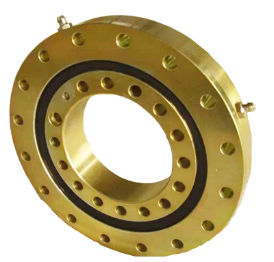
SET1157 Wheel hub Bearing 48.41×95.25mm: Tech Breakdown
When a fully loaded commercial trailer negotiates a sharp turn on uneven gravel, the wheel hub assembly absorbs massive combined forces. Vertical gravity pushes downward while lateral centrifugal force pulls outward, creating a complex stress vector at the tire-to-axle interface. This specific loading condition demands a component that can manage simultaneous radial and axial loads without generating excess heat or premature fretting corrosion. Engineers designing modern light truck and medium-duty trailer suspensions frequently specify a single-row tapered configuration housed within a compact envelope to meet these exact dynamic requirements.
At a glance
- When a fully loaded commercial trailer negotiates a sharp turn on uneven gravel, the wheel hub assembly absorbs massive
- Hub assemblies operate in some of the most punishing environments within mobile equipment manufacturing. Unlike spindle-
Operational Context Under Combined Stress Profiles
Hub assemblies operate in some of the most punishing environments within mobile equipment manufacturing. Unlike spindle-mounted ball units that primarily handle rotational freedom, this class of component must stabilize steering geometry while transmitting drive torque through differential outputs. The physical layout of the rolling elements dictates how effectively the unit channels load away from the axle stub. Excessive flex during cornering translates directly to accelerated tread wear and unpredictable handling feedback. Selecting the correct dimensional stack ensures that load paths align precisely with the host chassis suspension travel. Modern axle housings are engineered with tight housing bores and precise shoulder heights, meaning dimensional drift at the millimeter level can compromise entire subframe alignments.
Core Geometry and Dimensional Tolerances
Manufacturing consistency begins with the foundational measurements that define the part envelope. Every dimension listed below strictly governs mating interfaces between the bearing, the axle shaft, and the cast or stamped hub carrier.
| Specification | Value | Engineering Implication |
|---|---|---|
| Model Designation | SET1157 | Standardized series architecture identifier |
| Inside Diameter | 48.41 mm | Matches designated axle journal diameter |
| Outside Diameter | 95.25 mm | Controls outer ring seating in hub cavity |
| Overall Width | 30.16 mm | Dictates axial spacing and preload calibration |
| Number of Rows | One | Optimized for moderate combined load profiles |
| Precision Classification | PN (ABEC-1) | Baseline tolerance for general industrial duty |
Tolerances on these boundaries typically fall within standard manufacturing bands, yet deviations exceeding fifty microns can alter internal clearance. During assembly, technicians measure the actual shaft runout before pressing the inner ring. If the journal sits slightly off-center relative to the hub bore, dimensional accuracy becomes the primary variable preventing binding. The 30.16 mm profile also influences how much axial space remains for sealing systems and dust shields. Taller stacks require deeper housing pockets, while shorter variants demand precise spacer shim selection to maintain proper roller alignment.
Tapered Roller Raceway Mechanics
The structural backbone of this unit relies on a conical rolling element arrangement. Each individual cylinder tapers toward a common apex, which creates a theoretical point of rotation along the raceways. This geometric approach transforms pure radial compression into predictable axial thrust vectors. When the wheel turns, the contact patch shifts slightly, but the tapered surfaces maintain continuous metal-to-metal engagement across the full width of the rollers.
A single-row layout simplifies the kinematic chain compared to double-cone arrangements. Fewer contact patches mean reduced frictional heating during sustained highway cruising, yet the system still retains sufficient capacity for occasional heavy braking events. The raceway curvature is ground to match the roller flank angle, ensuring uniform pressure distribution rather than edge loading. Edge loading occurs when manufacturing inaccuracies cause rollers to pivot excessively, concentrating stress along the narrowest strip of the track. Proper contour grinding eliminates this failure mode entirely, extending fatigue life well beyond typical service intervals.
Stamping Steel Cage Dynamics
Component longevity often depends on secondary parts that engineers overlook. The retainer utilizes a precision-formed stamping steel cage instead of heavier machined alternatives. This manufacturing choice serves multiple functional purposes beyond simple cost reduction. Cold-formed steel exhibits superior elastic recovery compared to cut brass, allowing the cage fingers to absorb minor shock impacts without permanent deformation. The flexible lattice structure also promotes better lubricant channeling, as oil flows freely through the open mesh during high-frequency vibration cycles.
Weight reduction plays a critical role in rotating mass calculations. Lower inertial mass decreases the energy required to spin the assembly during acceleration phases. When evaluating fleet fuel efficiency metrics, even marginal reductions in unsprung rotating components accumulate significantly over hundreds of thousands of miles. Additionally, the stamped topology allows for optimized pocket sizing that securely locks each roller in place while maintaining adequate clearance for thermal expansion. Technicians should always verify that replacement retainers match the original tooth pitch and bend radius. Mismatched cages introduce uneven roller spacing, which instantly disrupts load distribution and accelerates surface spalling.
Precision Grade PN and Assembly Clearances
Quality classification systems exist to standardize performance expectations across different application tiers. The specified PN designation corresponds to a baseline tolerance band suited for general industrial duty cycles. This classification prioritizes functional reliability and dimensional stability over acoustic quietness or extreme rotational speeds. Applications requiring silence typically move up to tighter grading, whereas heavy commercial platforms accept broader clearances to accommodate thermal growth and mounting variations.
Internal clearance ranges dictate how tightly the rolling elements sit between the inner and outer rings before external forces are applied. Loose settings invite rattling and impact damage during idle operation, while overly tight configurations restrict lubricant circulation and trap heat. Technicians calibrate final assembly using specialized dial indicator setups to verify preload levels. The goal remains achieving zero axial play without inducing excessive drag torque. Proper clearance management prevents early lubricant breakdown and maintains consistent stiffness throughout the component operational lifespan. Verification protocols generally include:
- Measuring free rotation torque at room temperature before installing seals.
- Applying calibrated axial force to eliminate false clearance readings from housing deflection.
- Confirming smooth roller tracking under simulated load conditions to detect raceway irregularities.
- Documenting ambient humidity levels, as moisture absorption can temporarily swell cage materials.
Cylindrical Bore Interface Design
Installation methodology heavily influences initial quality control outcomes. This variant features a straightforward cylindrical bore configuration rather than a tapered internal geometry. The straight wall profile permits direct hydraulic or mechanical press installation onto matching shaft diameters. Operators benefit from simplified tooling requirements and reduced risk of cross-threading or misalignment during the fitting process. Automated production lines prefer this approach because consistent friction coefficients allow reliable cycle time prediction.
However, straight-bore assemblies demand strict surface preparation protocols. The mating shaft must achieve specific roughness parameters and cleanliness levels before engagement. Any embedded particulate or burr introduced during machining will create micro-gaps that evolve into fretting corrosion tracks over time. Preventive maintenance schedules should include periodic visual inspections of seal lips and grease fittings to catch early contamination signs before they compromise the running surfaces. When replacing units in older chassis architectures, verifying bore compatibility against current specifications prevents unintended interference issues.
Procurement Notes and Engineering Validation
Component sourcing requires careful verification against existing chassis documentation. Engineers routinely cross-check legacy part numbers against updated catalog listings to confirm dimensional equivalence and load rating continuity. Our facility maintains detailed mapping records to streamline identification processes, which you can explore further in our official bearing number reference. Maintaining accurate cross-reference data prevents costly procurement errors during emergency field replacements.
For project teams integrating these units into new vehicle architectures, reviewing our dedicated Wheel hub bearings category provides access to supplementary mounting kits, seal configurations, and compatible lubrication schemes. Always validate supplier documentation against original equipment manufacturer drawings before committing to bulk orders. Consistent engineering validation protects assembly integrity and ensures long-term field reliability across diverse operating climates. Partnering with a manufacturer focused on dimensional fidelity and material traceability, like FIJ Bearing, guarantees that every batch meets strict aerospace-grade inspection protocols scaled for automotive volume production.
Request a quote for SET1157 precision manufacturing and bulk fleet supply options.