
F-800695.TR4 Four row taper roller Bearing (635×900mm)
News & Updates
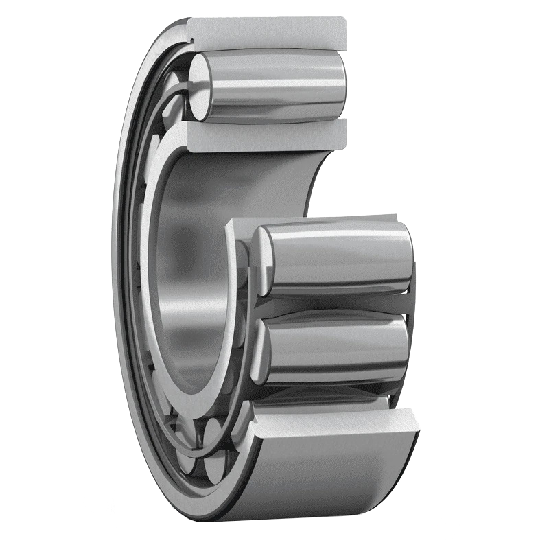
F-800695.TR4 Four row taper roller Bearing (635×900mm)
Boundary Dimensions and Physical Architecture
Model F-800695.TR4 | d:D:B = 635×900×660 mm | Mass: 1400 kg | Series: F-80..TR4 | Cage: Pin type. Each metric defines a critical spatial constraint for heavy machinery integration. The sixty-three-five millimeter cylindrical bore interfaces directly with standard shaft diameters, eliminating taper-induced fit complications during assembly. A nine-hundred-millimeter outside diameter establishes the primary housing contact perimeter, while the six-hundred-sixty-millimeter structural width spreads axial and radial stress evenly across the four complementary roller sets. This geometry prioritizes rigid support over compact packaging.
At a glance
- Specification: Value
- Inner Diameter (d): 635 mm
- Outer Diameter (D): 900 mm
- Overall Width (B): 660 mm
Explore compatible variants in our Four row taper roller bearings category.
| Specification | Value |
|---|---|
| Inner Diameter (d) | 635 mm |
| Outer Diameter (D) | 900 mm |
| Overall Width (B) | 660 mm |
| Mass | 1400 kg |
| Bore Configuration | Z (Cylindrical) |
| Roller Rows | Four |
| Dynamic Load Rating (Cr) | 18,597,685 N |
| Static Load Rating (Cor) | 43,997,761 N |
Load Capacity and Velocity Parameters
The eighteen-point-six meganewton dynamic rating confirms sustained resilience under complex multi-axis loading. Engineers must derive the equivalent dynamic bearing load before applying reliability factors, typically aiming for a target L10 life of ten thousand hours. The forty-four meganewton static threshold delineates permissible impact forces during emergency stops or jammed drive scenarios. Speed limitations are not dictated solely by RPM targets but by the n0 limiting speed curve, which accounts for centrifugal forces acting on the heavy pin cages. Operating past calculated nG boundaries generates excessive frictional heat, thinning the elastohydrodynamic lubricant film. Maintaining optimal viscosity requires precise temperature monitoring and forced circulation cooling systems. Consult standard bearing number reference literature to understand how the TR4 suffix adjusts clearance and preload characteristics relative to the original European design reference.
Mounting Procedure and Geometric Tolerances
Positioning a fourteen-hundred-kilogram assembly requires disciplined mechanical handling. Hydraulic press methods or targeted thermal induction remain the only viable installation routes. Direct mechanical shock destroys cage integrity and misaligns raceway contacts. Shaft fits should adhere to ISO k5 or k6 interference ranges, guaranteeing zero fretting corrosion at the interface. Housing bores demand G7 transition fits to lock the outer ring firmly against rotational creep. Flatness tolerances across the supporting shoulders must stay within zero-zero-one millimeters to preserve roller guidance. Misaligned mounting skewloads the tapered rollers, drastically reducing fatigue endurance. Execute the following verification steps prior to final commissioning:
- Measure housing bore runout and surface roughness Ra value
- Clean all mating surfaces with solvent-free lint wipes
- Apply consistent heating to the inner ring to achieve uniform thermal expansion
- Press-fit onto the shaft until fully backed against the stationary shoulder
- Secure locking devices to exact torque specifications using a calibrated indicator
Service Optimization and Technical Support
Predictive maintenance protocols extend functional lifespan significantly. Continuous spectral vibration monitoring detects early-stage spalling or lubricant breakdown. Regreasing frequencies depend heavily on operating environment severity and sealing efficiency. Corrosion inhibitors in modern greases protect exposed ferrous surfaces during prolonged idle periods. Our engineering division supplies precise calculation sheets for preload adjustment, lubricant dosing, and thermal expansion compensation tailored to your specific application envelope.
Request a formal quotation or specialized mounting schematic from FIJ. Reach out to our technical desk to optimize performance parameters for your industrial drive system.